
Intro
Finally, I get to play with my most complete Arduino starter kit and the Mega 2560. I am going to be using components I have never use before for the following projects. It is interesting to know that some of componenets are used in everyday devices you have in your home. With the ability to create sounds as output and take orientation and distance as input, we can really start to create some interesting experiments.
Active Buzzer
Components:
-
Elegoo Mega 2560 R3
-
Active buzzer
-
2 x F-M wires
One curcuit:
- Mega Pin 12 <-> Active buzzer <-> Mega GND
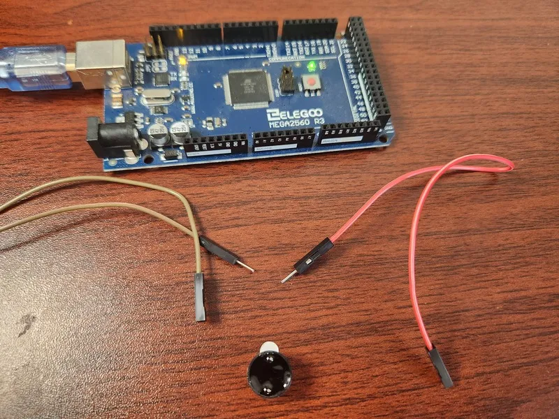
Active buzzers are basic sound emitters and date all the way back to 1831, when they were first invented by Joseph Henry and primarily used as doorbells. Electronic buzzers are DC-powered and have a polarity, meaning that the longer side is positive and the other negative. Nowadays they are widely used in computers, printers, photocopiers, alarms, electronic toys, automotive electronic devices, telephones, timers and other electronic products. Active buzzers are really simple to use as they can only create a fixed frequency. This is because it has a built-in oscillating source, so it will generate a sound when electrified.
int buzzer = 12;
void setup() {
  pinMode(buzzer, OUTPUT);
}

void buzz(int frequency) {
  int wait = 1000 / frequency / 2;
  for(int i = 0; i < 1000; i += 2 * wait) {
    digitalWrite(buzzer, HIGH);
    delay(wait);
    digitalWrite(buzzer, LOW);
    delay(wait);
  }
}

void loop() {
  buzz(500);
  buzz(250);
  buzz(100);
  buzz(50);
}
Passive Buzzer
Components:
-
Elegoo Mega 2560 R3
-
Passive buzzer
-
2 F-M wires
One curcuit:
- Mega Pin 8 <-> Passive buzzer <-> Mega GND
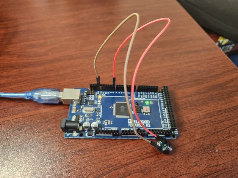
The working principle of a passive buzzer is using PWM generating audio to make the air vibrate. Appropriately changed as long as the vibration frequency, it can generate different sounds. The difference between the two buzzers is that an active buzzer has a built-in oscillating source, so it will generate a sound when electrified. A passive buzzer does not have such a source so it will not buzz if DC signals are used; instead, you need to use square waves to drive it.
The active buzzer is often more expensive than the passive one because of multiple built-in oscillating circuits. For this project, we need to include a basic header file that includes constants for the different pitches we need to use like the following: #define NOTE_B0 31.
#include "pitches.h"

int melody[] = { NOTE_C5, NOTE_D5, NOTE_E5, NOTE_F5, NOTE_G5, NOTE_A5, NOTE_B5, NOTE_C6 };
int buzzer = 8;

void setup() {
    pinMode(buzzer, OUTPUT);
}

void loop() {
  for (int note = 0; note < 8; note++) {
    tone(buzzer, melody[note], 500);
    delay(1000);
  }
  delay(2000);
}
Tilt Sensor
Components:
-
Elegoo Mega 2560
-
Tilt sensor
-
2 F-M wires
One curcuit:
- Mega Pin 2 <-> Tilt sensor <-> Mega GND
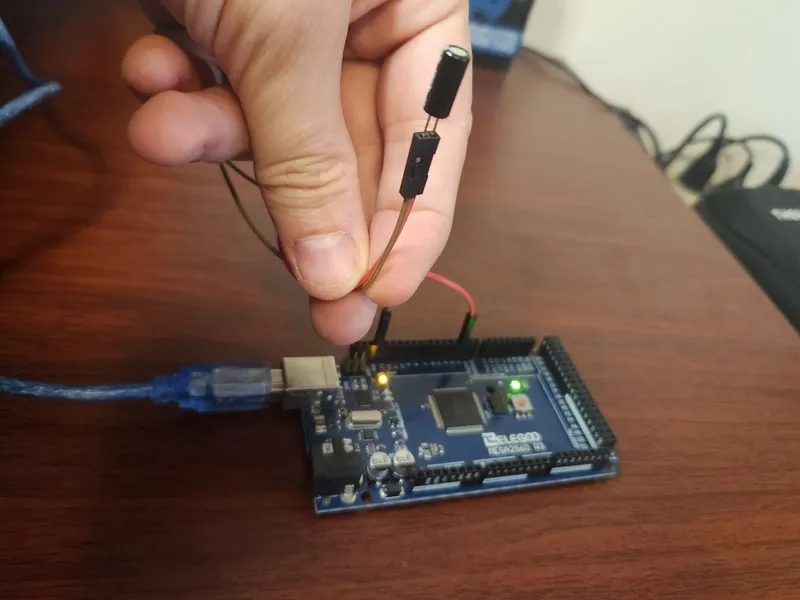
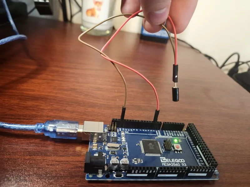
Tilt sensors allow you to detect orientation or inclination. They are small, inexpensive, low-power and easy-to-use. If used properly, they will not wear out. Their simplicity makes them popular for toys, gadgets and appliances.
They are usually made up of a cavity of some sort with a conductive free mass inside, such as a blob of mercury or rolling ball. One end of the cavity has two conductive elements. When the sensor is oriented so that that end is downwards, the mass rolls onto the poles and shorts them, acting as a switch throw.
While not as precise or flexible as a full accelerometer, tilt switches can detect motion or orientation. Another benefit is that the big ones can switch power on their own. Accelerometers, on the other hand, output digital or analog voltage that must then be analyzed using extra circuitry.
For this project, our board LED turns on when the sensor is pointing up, and off otherwise.
const int ledPin = 13;
const int tiltBallSwitch = 2;

void setup() {
  pinMode(ledPin, OUTPUT);
  pinMode(tiltBallSwitch, INPUT);
  digitalWrite(tiltBallSwitch, HIGH);
}

void loop() {
  int digitalVal = digitalRead(tiltBallSwitch);
  if(HIGH == digitalVal) {
    digitalWrite(ledPin, LOW);
  } else {
    digitalWrite(ledPin, HIGH);
  }
}
Servo Motor
Components:
-
Elegoo Mega 2560 R3
-
Servo (SG90)
-
3 M-M wires
One curcuit:
-
Mega Pin 9 <-> Servo Signal
-
Mega 5v <-> Servo VCC
-
Mega GND <-> Servo GND
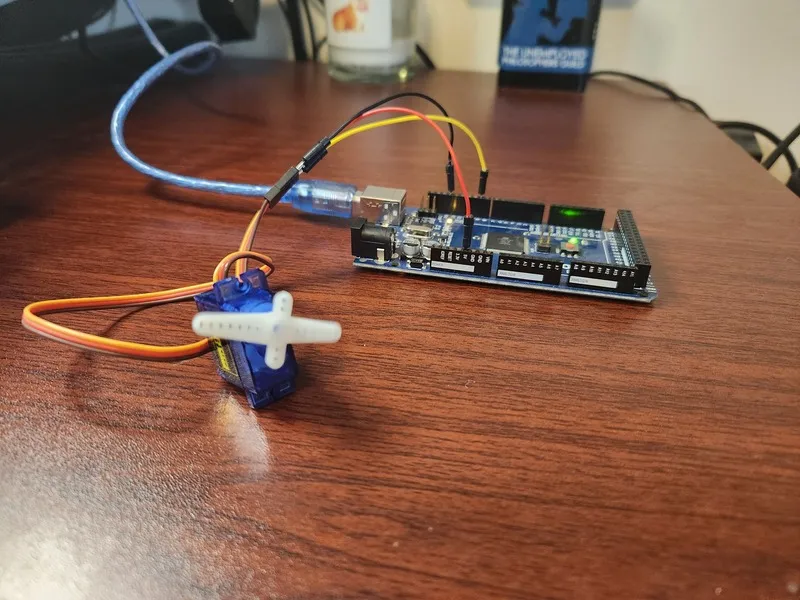
Servo is a type of geared motor that can only rotate 180 degrees. It is controlled by sending electrical pulses. These pulses tell the servo what position it should move to. The Servo has three wires, of which the brown one is the ground wire, the red one is the power wire, and the orange one is the signal wire. This project requires us to import a much more complicated headers file in order to get started.
#include <Servo.h>
Servo myservo;

void setup() {
  myservo.attach(9);
  myservo.write(0);
}

void loop() {
  myservo.write(0);
  delay(1000);
  myservo.write(90);
  delay(1000);
  myservo.write(180);
  delay(1000);
  myservo.write(90);
  delay(1000);
}
Ultrasonic Sensor
Components:
-
Elegoo Mega 2560 R3
-
Ultrasonic sensor module
-
4 F-M wires
One curcuit:
-
Mega Pin 12 <-> Ultrasonic sensor module VCC
-
Mega Pin 11 <-> Ultrasonic sensor module Trig
-
Mega Pin 10 <-> Ultrasonic sensor module Echo
-
Mega GND <-> Ultrasonic sensor module GND
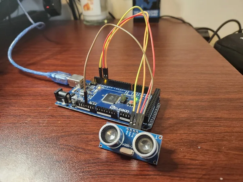
An ultrasonic sensor, like the HC-SR04, works on the principle of sending and receiving sound waves to measure the distance between the sensor and an object.
-
Components of the Sensor: The HC-SR04 sensor module consists of ultrasonic transmitters, a receiver, and a control circuit. The transmitter emits high-frequency sound waves, while the receiver detects the reflected sound waves.
-
Triggering the Sensor: To initiate a distance measurement, you need to send an IO trigger signal to the sensor. This trigger signal should be at least 10 microseconds in duration and set to a high-level.
-
Emitting Ultrasonic Waves: When the trigger signal is received, the module automatically sends out a burst of eight ultrasonic sound waves at a frequency of 40 kHz. These sound waves travel through the air until they encounter an object.
-
Detecting Echo: If these sound waves hit an object and bounce back to the sensor, the receiver detects them as an echo. The echo is essentially a pulse signal, and its duration is proportional to the distance between the sensor and the object.
-
Calculating Distance: The sensor measures the time interval between sending the trigger signal and receiving the echo signal. This time interval is measured in microseconds (us).
To calculate the distance to the object, you can use the following formula:
D (in centimeters) = (Time interval in microseconds) / 58The sensor automatically performs these calculations for you.
- Measurement Cycle: The sensor provides accurate distance measurements with a ranging accuracy of up to 3mm. To ensure reliable readings, it is recommended to use a measurement cycle of over 60 milliseconds. This interval helps prevent interference or overlap between the trigger signal and the echo signal from the previous measurement.
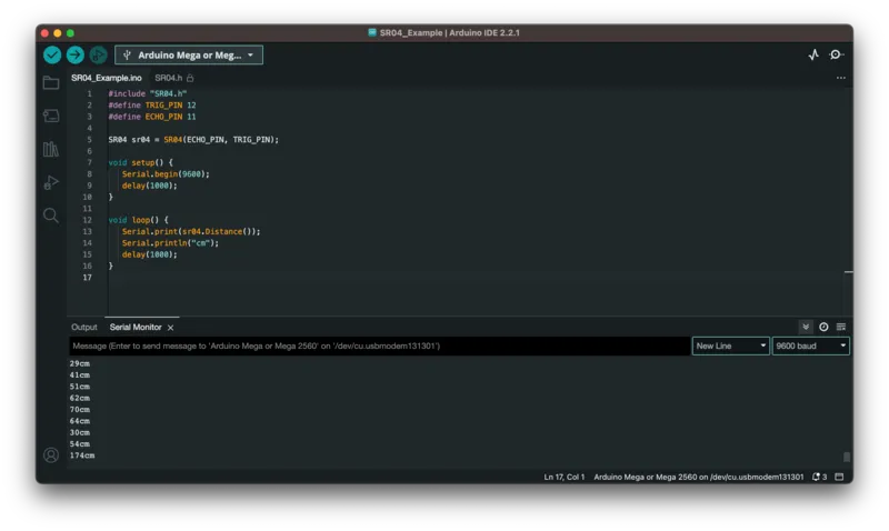
#include "SR04.h"
#define TRIG_PIN 12
#define ECHO_PIN 11

SR04 sr04 = SR04(ECHO_PIN, TRIG_PIN);

void setup() {
   Serial.begin(9600);
   delay(1000);
}

void loop() {
   Serial.print(sr04.Distance());
   Serial.println("cm");
   delay(1000);
}
Conclusion
As I am sure you noticed, a lot of the projects dealt with sound. Weither it was audible to the human ear or not, it still have its uses in building sophisticated projects. I am looking forward to the next set of projects where I can experiment with more interesting inputs and outputs.