
Introduction
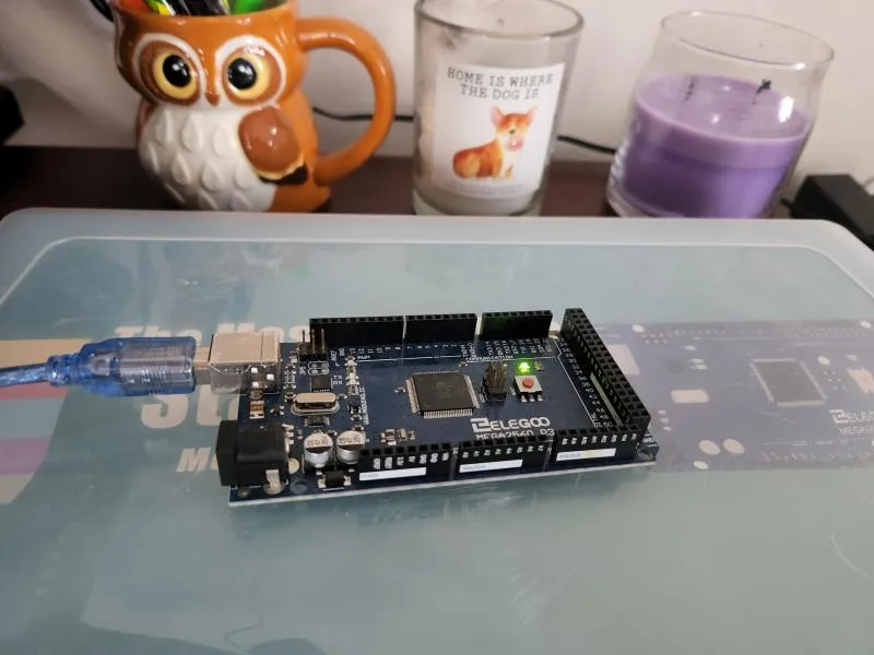
I am really excited to finally be working with my Elegoo Most Complete Starter Kit and Mega 2560. I have had this for a little over a year but have not really had a chance to get far in the tutorials. I am finally going to have a go at it and share my experience as I work through it. If you want to follow along get a box for yourself.
The MEGA2560 complete starter kit with more than 200 components (60 unique components), premium quality, and 100% Compatible with Arduino IDE. Its free pdf tutorial has over 35 lessons. It includes components with pin headers and a bread board so no soldering is required. It seems like it will be a great kit to learn and prototype with.
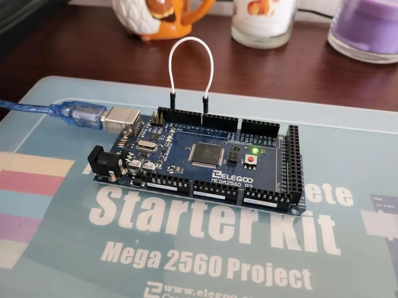
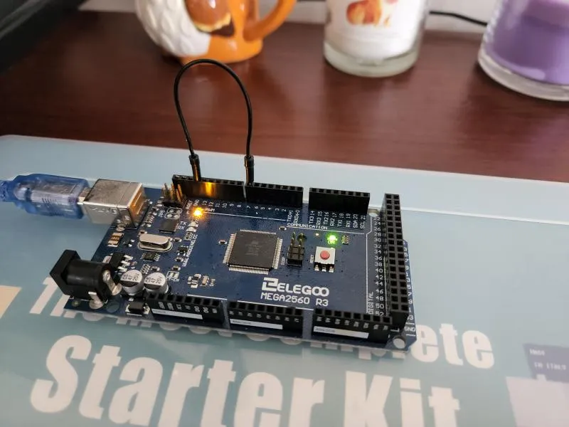
The MEGA 2560 R3 board has rows of connectors on two sides that are used to connect electronic devices and add-ons that extend its capability. It also has a single LED you can control from your sketches. This LED is built into the MEGA 2560 R3 board and its simply the LED labeled “L” on the board.
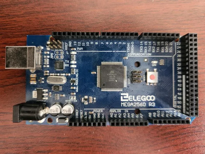
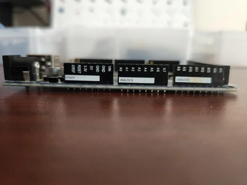
If you ever get confused about which pin is which be sure the look at the side for a more accurate labeling. Looking from overhead is always a little confusing for me and I almost always get it wrong.
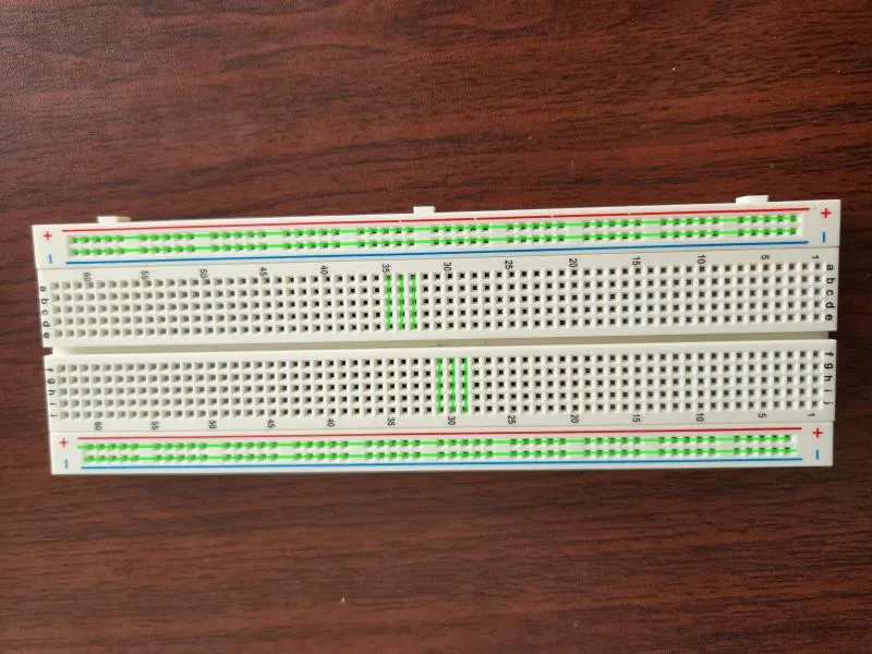
As mentioned, the kit also comes with a standard 830 tie-points breadboard. This is a great tool for prototyping but can be a little confusing as to how it works at first. First lets talk vocabulary:
-
Terminal Strips - This is typically where you put your components. Any components connected to the same strip share a current. You can see below the shared currents indicated by vertical green lines.
-
Power Rails - This is typically where you put your ground and power source. You then connect these to your terminal strips. You can see below the shared currents indicated by horizontal green lines.
-
DIP (Dual in-line Package) Support - This is where you can place integrated circuits since they are usually manufactured to nicely fit over the gap.
Basic Blink Program
Components:
- MEGA 2560
// This function runs once as your programs starts up
void setup() {
  // You can initialize variables and enable pins for input and output
  pinMode(LED_BUILTIN, OUTPUT);
}

// This function runs over and over again forever
void loop() {
  // Turn the light on
  digitalWrite(LED_BUILTIN, HIGH);
  // Wait 1 second
  delay(1000);
  // Turn the light off
  digitalWrite(LED_BUILTIN, LOW);
  delay(1000);
}
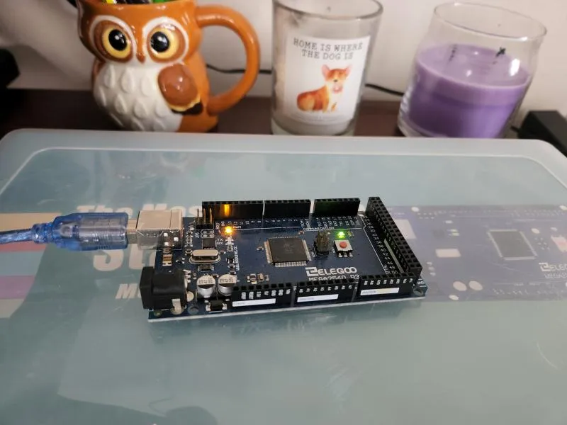
This simple program should turn on the chips test LED for 1 second, then off for 1 second, then repeat forever. If you get this result then you are good to go for future projects. If you have any issues it is likely you just need to configure your connections. When I initially had trouble connecting it was because I had to go to Tools and set my board, processor, and port to match my version of Arduino (In this case they pretty much all had MEGA2560 in their name). Below you will see what it looks like when the (yellow) LED is on and off.
Testing Wires
Sometimes the equipment you have simply will not work. I had to learn this the hard way as I struggled to rewire my components in every way I could think of when I could have saved some time by just switching components.
#define TEST 7

void setup() {
  pinMode(LED_BUILTIN, OUTPUT);
  pinMode(TEST, INPUT_PULLUP);
}


void loop() {
  digitalWrite(LED_BUILTIN, digitalRead(TEST));
}
After uploading the test program you should see that the debug light instantly turns and stays on. Simply connect any wire from Pin 7 to the GRD Pin. If the light turns off then you got a good wire. If the light remains on throw that wire away immediately. This happens because the INPUT_PULLUP forces the Pin 7 to send a HIGH signal unless it detects GRD. When you have a good wire connected from Pin 7 to GRD we end up with a LOW signal from the digitalRead which makes the debug light turn off. The pictures below show a functioning white wire and a faulty black wire.
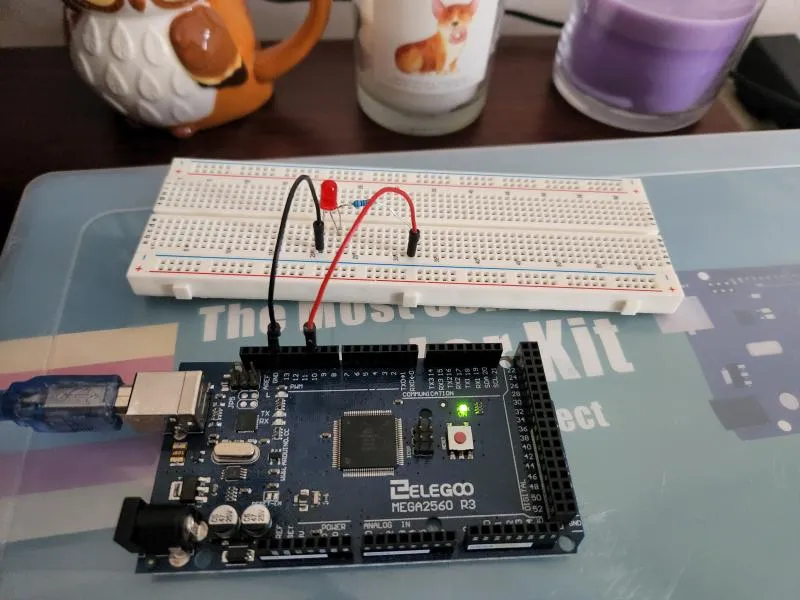
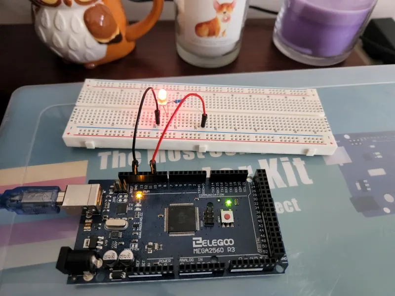
LEDs and Resistors
Components and Configuration:
-
LED - Anode (+) <-> J:30, Cathode (-) <-> J:31
-
Resistor - E:30, F:30
-
MEGA 2560 - GRD <-> F:31, Pin 13 <-> A:30
One current:
- MEGA 2560 Pin 13 -> Resistor -> LED -> MEGA 2560 GRD
LEDs
LEDs (light-emitting diode) are really helpful in debugging code and connections. Better yet, they use very little electricity and they pretty much last forever. You need to know a little bit about an LED first before you can get it to light up. Most importantly is knowing which side is the anode (positive side) and the cathode (negative side). There are actually two ways to determine this. First you can look at the length of the legs, the longer leg is usually the anode/positive leg. Another way is to look at the LED from above, the LED is mostly round when viewed from above, except a small portion, which is flat, this is the cathode/negative leg. There is no risk in wiring the LED the wrong direction, it simply will not work. There is risk however in putting an LED in a direct circuit, without a resistor you run the risk of permanently damaging your LED and burning it out.
Resistors
Resistors (Ω) resist the flow of electricity, the higher the value of the resistor, the more it reduces the current flowing through the circuit. This means that the stronger your resistance the weaker your light will be since it will not get as much current. Resistors will work no matter which way the current is flowing so there is no messing up the configuration when dealing with them. It is important to use resistors no matter the circuit in order to prevent permanent component damage.
For this project, reuse the code from the Blink project. You will notice that the LED lights up at the same time as the built in LED. Look at the images below to see what this should look like in action. You can also reuse this project anytime you want to test an LED, simply use the LED you wish to test for the circuit.
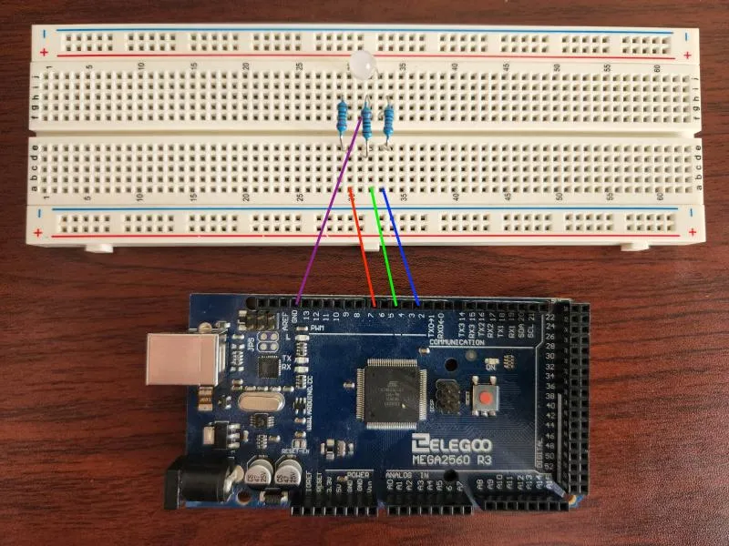
Animating the RGB LED
Components and Configuration:
-
RGB LED - R <-> J:30, C <-> J:31, G <-> J:32, B <-> J:33
-
3 Resistors - E:30 <-> F:30, E:32 <-> F:32, E:33 <-> F:33
-
MEGA 2560 - GRD <-> F:31, Pin 7 <-> A:30, Pin 5 <-> A:32, Pin 3 <-> A:33
Three circuits
-
Red: MEGA 2560 Pin 7 -> Resistor -> LED -> MEGA 2560 GRD
-
Green: MEGA 2560 Pin 5 -> Resistor -> LED -> MEGA 2560 GRD
-
Blue: MEGA 2560 Pin 3 -> Resistor -> LED -> MEGA 2560 GRD
#define RED 7
#define GREEN 5
#define BLUE 3

#define BRIGHTEST 255
#define MAX_INDEX 99
#define SIZE (MAX_INDEX / 3)

void setup() {
  pinMode(RED, OUTPUT);
  pinMode(GREEN, OUTPUT);
  pinMode(BLUE, OUTPUT);
}

int index = 0;

void loop() {
  double red = 0;
  double green = 0;
  double blue = 0;
  // this is where we are in any individual animation, the value is [0 to 1)
  double value = (index % SIZE) / ((double) SIZE);
  if(index < SIZE) {
    // first we do red to green
    red = 1 - value;
    green = value;
  } else if(index < SIZE * 2) {
    // then we do green to red
    green = 1 - value;
    blue = value;
  } else {
    // finally we finish off with blue to red
    blue = 1 - value;
    red = value;
  }
  analogWrite(RED, red * BRIGHTEST);
  analogWrite(GREEN, green * BRIGHTEST);
  analogWrite(BLUE, blue * BRIGHTEST);
  // advance the color index
  index = (index + 1) % MAX_INDEX;
  delay(1000 / 20);
}
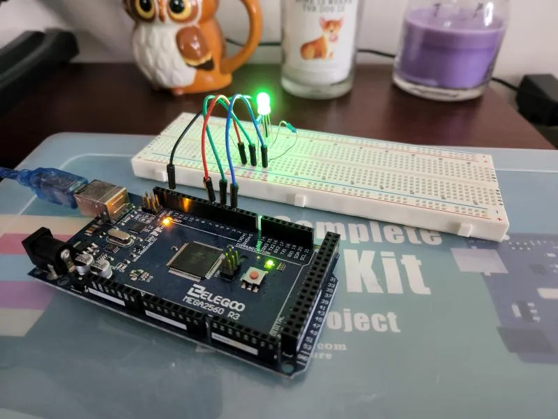
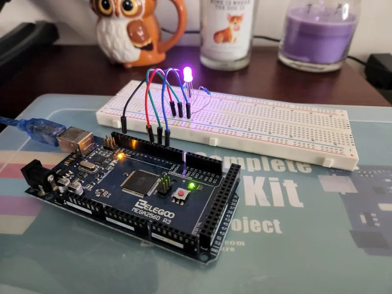
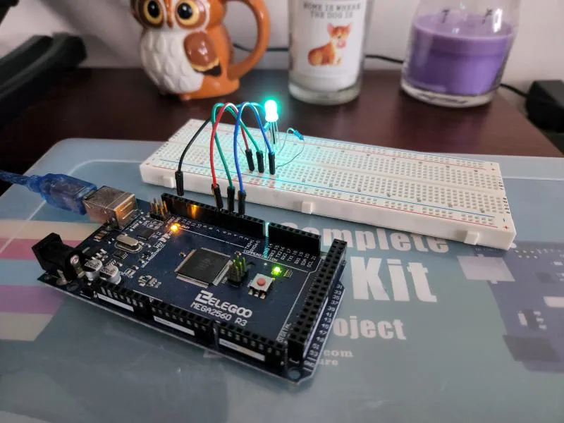
RGB LEDs
A great way to add some color to your project is by adding RGB LEDs. They are essentially 3 normal LEDs combined into one. With it you can make just about every color combination by mixing different colors of light at different ratios. The type that comes with the kit has a Common Cathode, meaning that a single lead (the longest one) should be connected to the ground and the rest to a power source. Just like the other LEDs, this one will also need a resistor for each positive pin.
The program above animates the colors from red to green to blue and finally back to red. Look below to see the different states.
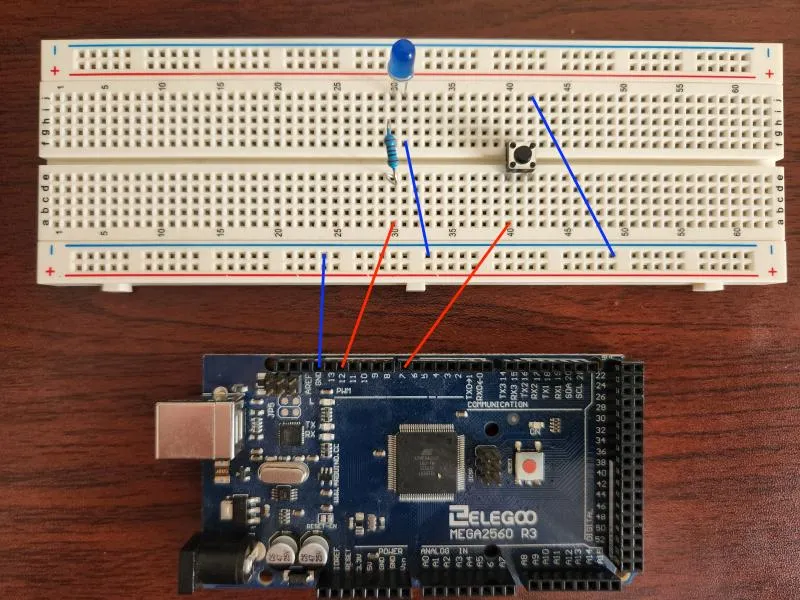
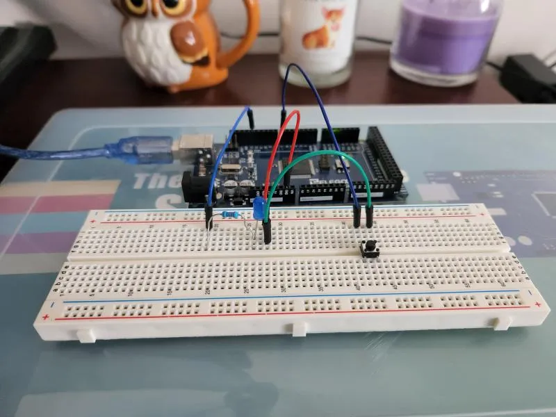
Simple Button for User Input
Components and Configuration:
-
LED - Anode (+) <-> J:30, Cathode (-) <-> J:31
-
Resistor - E:30 <-> F:30
-
Button - E:40/F:40 <-> E:42/F:42
-
MEGA 2560 - GRD <-> BB-GRD, Pin 12 <-> A:30, Pin 7 <-> A:40
-
Breadboard - BB-GRD <-> J:42
Two circuits:
-
MEGA 2560 Pin 12 -> Resistor -> LED -> MEGA 2560 GRD
-
MEGA 2560 Pin 7 -> Button -> MEGA 2560 GRD
#define LIGHT 12
#define BUTTON 7

void setup() {
  pinMode(LIGHT, OUTPUT);
  pinMode(BUTTON, INPUT_PULLUP);
}

// The light starts off
boolean isOn = false;
boolean triggered = false;

void loop() {
  // Conditionally change the light's signal
  if(isOn) {
    digitalWrite(LIGHT, HIGH);
  } else {
    digitalWrite(LIGHT, LOW);
  }
  // If we detect a button press AND we have not detected it already
  if(digitalRead(BUTTON) == LOW && !triggered) {
    isOn = !isOn;
    triggered = true;
  } else {
    // We can now start listening for a new click
    triggered = false;
  }
}
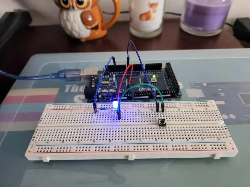
Buttons
Buttons can work many different ways. The ones include in the kit come with two internal connections when the button is not pressed. Essentially the legs that are pointing to each other are already connected. Pressing the button makes it so that all four legs are connected. Pressing the button completes the circuit to ground which we use for detecting the press in code.
I approached this project a little bit differently than the suggested tutorial. Instead of two buttons, one for on and another for off, I opted for a toggle button. Each time you press the button, the light will toggle its state. Look below to see the working configuration.
Conclusion
These projects were very visual. It looks like the next few projects will be more audible and visually exciting.